m2C2: mmWave-Camera Calibration via Human Pose
Abstract
This paper presents m2C2, a markerless calibration method for estimating the 6-DoF extrinsic transformation between mmWave radar and RGB cameras using natural human joint poses. Despite the growing demand for robust multi-sensor perception systems, calibration remains challenging, not only because traditional calibration methods rely on controlled environments and manual, target-based setups, but because mmWave radar measurements are inherently sparse and noisy, making stable geometric correspondences difficult. m2C2 addresses these limitations by utilising natural human motion as a shared calibration domain, enabling automated recalibration without dedicated calibration targets. Our framework jointly optimises the extrinsic translation and rotation by minimising an objective function over 2D and 3D human keypoints. Our approach mitigates the noise and sparsity of mmWave data through a novel bone-length scaling mechanism, jointly optimised with the extrinsics, that absorbs systematic skeleton-proportion errors from the radar pose estimator, supported by a confidence-weighted reprojection loss. Verified through experiments on a real-world dataset, m2C2 achieves an average translation error of 13.23 cm and a rotation error of 1.51°, relative to the ground truth, outperforming baseline PnP methods. Sensitivity analysis further demonstrates the method's robustness by displaying comparable results across different parameters, configurations, and subjects. These results demonstrate that m2C2 provides a robust and practical alternative to traditional marker-based calibration.
Method
m2C2 estimates the rigid transformation \(T = \{R, \mathbf{t}\}\) that maps points from the mmWave radar frame to the camera frame. Instead of matching raw radar points to pixels, both sensors are first converted into the same representation: the joints of an SMPL human skeleton. The joint streams are aligned in time, and the extrinsics are then solved by minimising a confidence-weighted reprojection error while jointly optimising per-bone length scale factors. Since the method only requires human pose, it can be applied to any sensor pair that supports SMPL pose estimation.
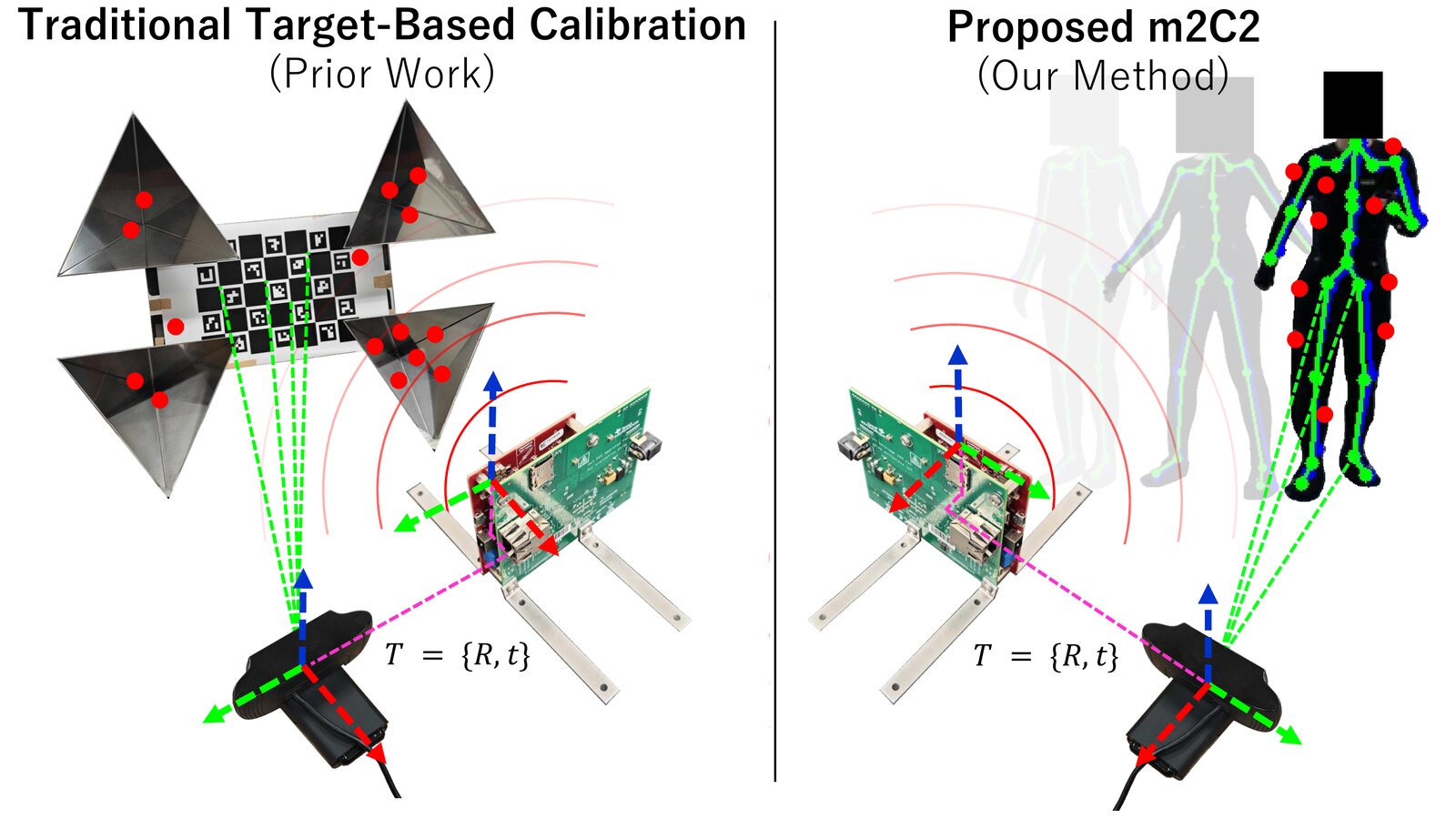
Conventional target-based calibration (left) requires a board with a ChArUco pattern for the camera and corner reflectors for the radar. m2C2 (right) removes the physical target and uses natural human joint poses as the shared reference for aligning the two sensors.
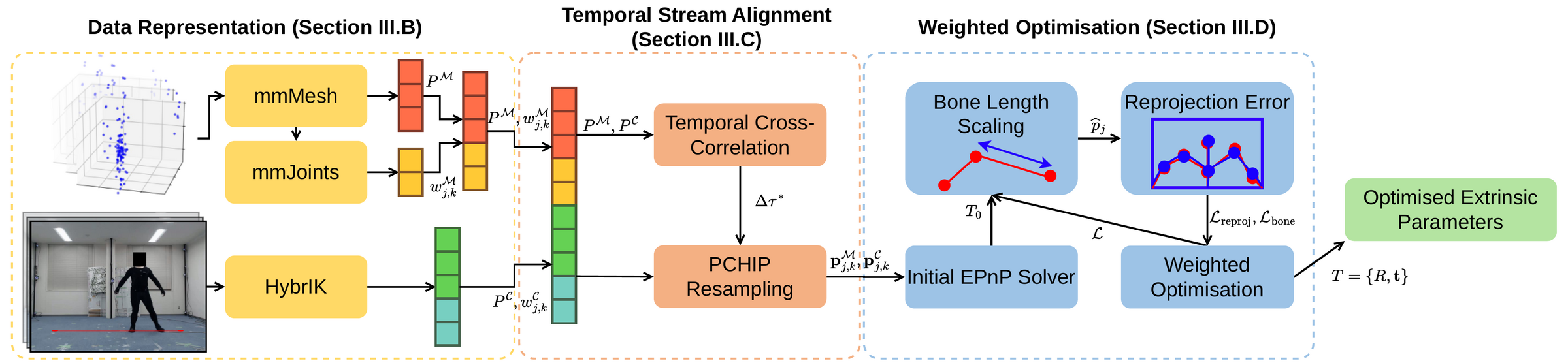
Overview of the m2C2 framework. Raw data from the mmWave radar and RGB camera are processed independently to extract 3D and 2D SMPL keypoints. The streams are temporally aligned using motion-signature cross-correlation and PCHIP resampling. Finally, the extrinsic parameters \((R, \mathbf{t})\) are estimated by minimising the confidence-weighted reprojection error, accounting for optimisable bone-length scaling.
Shared SMPL representation
3D joint positions \(\mathbf{p}^{\mathcal{M}}_{j,k}\) are estimated from the radar point cloud with mmMesh, and mmJoints adds a per-joint confidence \(w^{\mathcal{M}}_{j,k}\). On the camera side, HybrIK provides 2D joint positions \(\mathbf{p}^{\mathcal{C}}_{j,k}\), with a confidence \(w^{\mathcal{C}}_{j,k}\) taken from the heatmap peak. Both outputs are truncated to the same \(N = 22\) joints so every radar joint has a one-to-one partner in the image.
Temporal stream alignment
The two sensors have different latencies, leaving a sub-frame offset \(\Delta\tau\) between the streams. Joint positions cannot be compared directly across 3D and 2D, but joint speeds correlate well once the streams are aligned. We therefore compute a motion signature from the median speed of six robust joints \(\mathcal{J}\) (pelvis, ankles, neck and shoulders), normalise it with the median absolute deviation, and find the offset that maximises the continuous cross-correlation:
\[ \sigma[k] = \operatorname*{median}_{j \in \mathcal{J}} \left\| \mathbf{p}_{j,k} - \mathbf{p}_{j,k-1} \right\|_2, \qquad \Delta\tau^{*} = \operatorname*{arg\,max}_{\Delta\tau \in [-w,\, w]} \sum_{k} \tilde{\sigma}^{\text{3D}}(\tau_k)\, \tilde{\sigma}^{\text{2D}}(\tau_k + \Delta\tau) \]
The radar stream is then resampled at the shifted camera timestamps using piecewise cubic Hermite interpolation (PCHIP).
Confidence-weighted reprojection
Each radar joint is projected into the image with the current estimate of \(T\), and compared with the matching 2D joint. The error of every joint is weighted by the geometric mean of the min–max normalised confidences from both sensors, so a joint that is unreliable in either modality has little influence:
\[ e_{j,k} = \left\| \pi(T, \mathbf{p}^{\mathcal{M}}_{j,k}) - \mathbf{p}^{\mathcal{C}}_{j,k} \right\|_2, \qquad w_{j,k} = \sqrt{\bar{w}^{\mathcal{M}}_{j,k}\, \bar{w}^{\mathcal{C}}_{j,k}} \] \[ \mathcal{L}_{\text{reproj}} = \sum_{k} \sum_{j} w_{j,k}\, \rho(e_{j,k}) \]
where \(\rho\) is the Huber loss. An initial estimate \(T_0\) is obtained with RANSAC-based EPnP over all joint pairs.
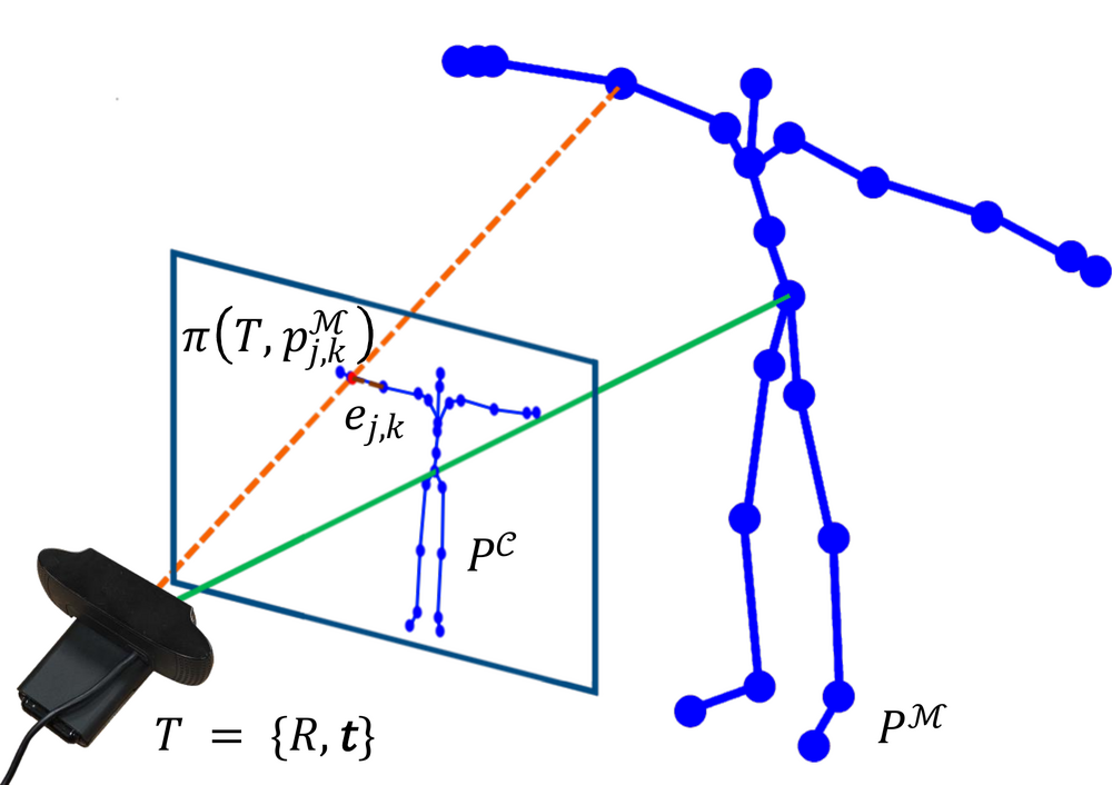
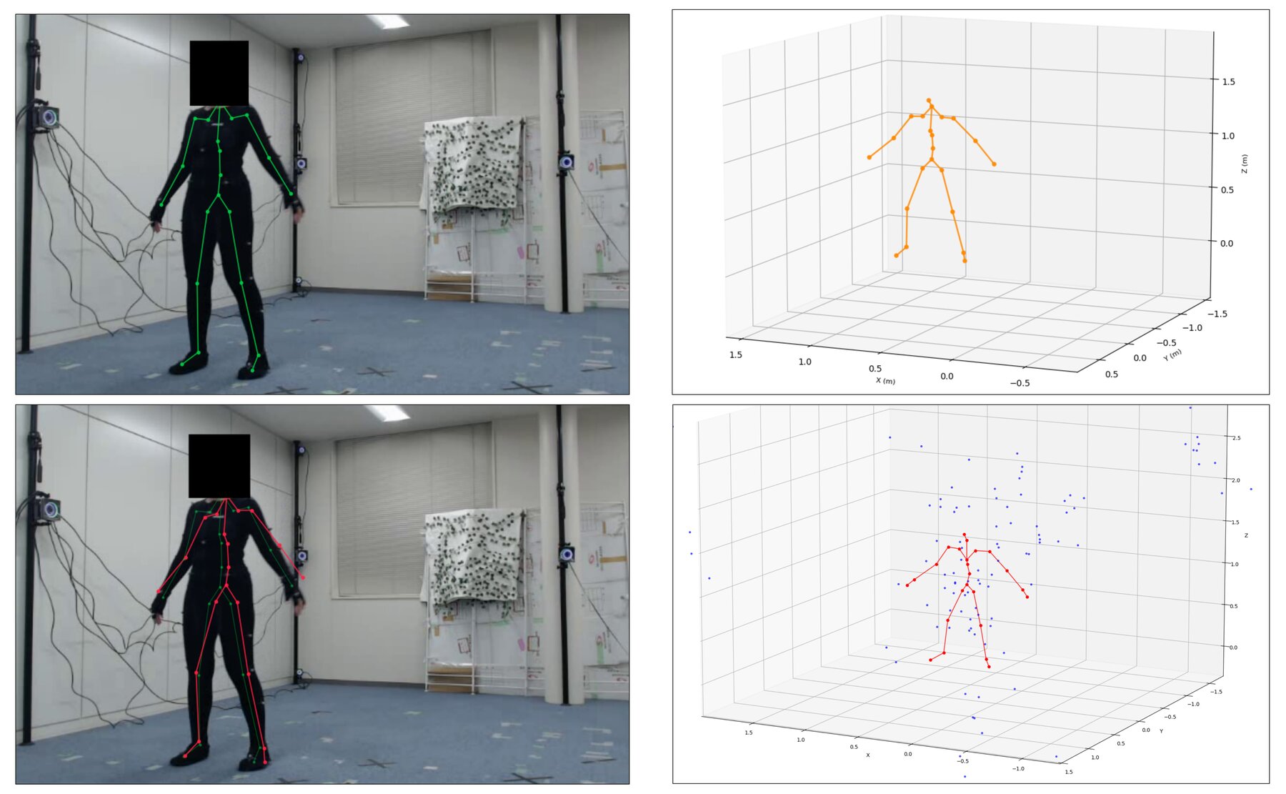
Radar keypoints \(P^{\mathcal{M}}\) (red) are projected with \(T\) and compared with the RGB keypoints \(P^{\mathcal{C}}\) (blue).
Bone-length scaling
mmMesh and HybrIK estimate skeletons with systematically different proportions. If left uncorrected, the optimiser compensates for this by moving the camera, which biases the extrinsics. m2C2 instead rescales each bone along the kinematic chain with a learnable factor \(s_j = \exp(\lambda_j)\), which changes bone lengths while preserving joint angles. The scale factors are optimised jointly with \(T\), with a regulariser that keeps them close to the estimator's original lengths:
\[ \hat{\mathbf{p}}_j = \hat{\mathbf{p}}_{\mathrm{pa}(j)} + s_j \left( \mathbf{p}_j - \mathbf{p}_{\mathrm{pa}(j)} \right), \qquad T^{*}, \{\lambda_j^{*}\} = \operatorname*{arg\,min}_{T,\, \{\lambda_j\}} \; \mathcal{L}_{\text{reproj}} + \lambda_{\text{reg}} \sum_{j=1}^{N} \lambda_j^{2} \]
Dataset
We recorded a real-world mmWave–RGB dataset with five subjects (four male, one female) of diverse body types. Each subject performed two motion sequences under four sensor configurations that vary the horizontal and vertical offset and the rotation between the radar and camera. Results are averaged over 20 recorded sequences.
Each sequence is 3,000 frames (about 5 minutes at 10 FPS), recorded at 640×480 with subjects 1.6–5.0 m from the sensors performing lateral and radial walking. Ground-truth extrinsics come from a dedicated calibration take with a target-based board, captured at 1920×1080 before each recording while the sensors stayed fixed.
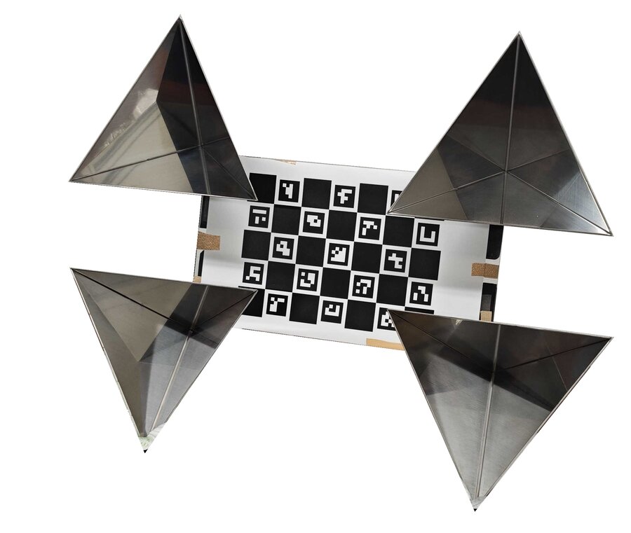
Target-based calibration board (ChArUco pattern with four corner reflectors), used only to obtain ground truth.
Quantitative Results
We compare the estimated extrinsics against the target-based ground truth using the translation error \(E_t\) (cm), the rotation error \(E_R\) (°) and the mean reprojection error (MRE, px). Across all 20 sequences, m2C2 reaches 13.23 cm and 1.51°, compared with 23.72 cm and 2.48° for a standard PnP baseline on the same joints.
Ablation study
| Method | \(E_t\) (cm) ↓ | \(E_R\) (°) ↓ | MRE (px) ↓ |
|---|---|---|---|
| Baseline (PnP) | 23.72 | 2.48 | 9.05 |
| Baseline (PnP) + Time Shift | 23.32 | 2.39 | 6.36 |
| m2C2 (Full) | 13.23 | 1.51 | 5.41 |
| w/o Time Shift | 14.21 | 1.54 | 8.29 |
| w/o Conf. Weighting | 13.31 | 1.55 | 5.41 |
| w/o Bone Scaling | 18.13 | 1.95 | 6.36 |
| w/o Conf. + Bone | 18.28 | 1.97 | 6.35 |
| w/o Time + Bone | 18.45 | 2.03 | 9.03 |
Bone-length scaling is the largest single contributor, accounting for 4.90 cm of the reduction in translation error. Temporal alignment improves translation error by 0.98 cm but reprojection error by 2.88 px, which reflects the small inter-stream offsets in this dataset (\(|\Delta\tau| \le 0.3\) s). Confidence weighting contributes a further 0.08 cm.
Sensor configurations
| Configuration | \(E_t\) (cm) ↓ | \(E_R\) (°) ↓ | MRE (px) ↓ |
|---|---|---|---|
| Horizontal Offset (L/R) | 15.14 | 1.74 | 7.60 |
| Horizontal Offset (F/B) | 11.27 | 0.58 | 4.28 |
| Vertical Offset | 11.31 | 0.42 | 4.21 |
| Vertical Offset + Rotation | 14.82 | 3.13 | 5.33 |
Errors are higher for the lateral and rotated configurations. The reprojection objective has a depth–scale ambiguity that is only resolved when the subject moves along the viewing direction, so purely side-to-side motion is the main failure case of the method.
Robustness
| Subject | \(E_t\) (cm) ↓ | \(E_R\) (°) ↓ | MRE (px) ↓ |
|---|---|---|---|
| Subject A | 13.77 | 1.14 | 4.16 |
| Subject B | 14.87 | 0.84 | 4.53 |
| Subject C | 17.46 | 2.81 | 5.35 |
| Subject D | 10.57 | 2.39 | 7.79 |
| Subject E | 10.55 | 0.72 | 5.21 |
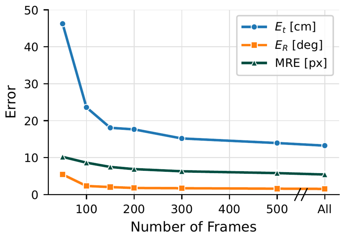
Accuracy versus the number of sampled frames. Errors drop steeply up to about 150 frames and level off after about 500.
| \(\lambda_{\text{reg}}\) | \(E_t\) (cm) ↓ | \(E_R\) (°) ↓ | MRE (px) ↓ | Bone Dev. (%) ↓ |
|---|---|---|---|---|
| \(10^{-4}\) | 13.04 | 1.51 | 5.41 | 16.93 |
| \(10^{-3}\) | 13.04 | 1.51 | 5.41 | 16.92 |
| \(10^{-2}\) | 13.06 | 1.51 | 5.41 | 16.81 |
| \(10^{-1}\) | 13.23 | 1.51 | 5.41 | 15.96 |
| \(10^{0}\) | 14.29 | 1.58 | 5.45 | 11.95 |
| \(10^{1}\) | 17.25 | 1.77 | 5.74 | 5.81 |
Results are consistent across subjects, and translation error stays within 13.04–13.23 cm for \(\lambda_{\text{reg}} \le 10^{-1}\). With very strong regularisation (\(10^{1}\)) the scale factors are pushed towards 1 and accuracy approaches the "w/o Bone Scaling" ablation.
Qualitative Results
BibTeX
@inproceedings{shilton2026m2c2,
  title     = {m2C2: mmWave-Camera Calibration via Human Pose},
  author    = {Shilton, Jack and Isogawa, Mariko and Sakurada, Ken},
  booktitle = {Proceedings of the IEEE/RSJ International Conference on Intelligent Robots and Systems (IROS)},
  year      = {2026}
}
Acknowledgements
This work was partially supported by JSPS KAKENHI (B) 26K02929.